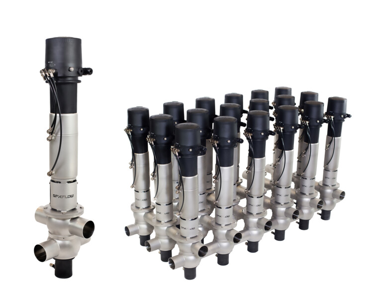
D4 / DA4 Series - Double Seat Mixproof Valves
FEATURES
The next generation of mixproof valve technology is the result of continued development from both APV and Waukesha Cherry-Burrell process technologies. Used for the reliable separation of dissimilar fluids, the D4 Series helps fulfill todays customer demands for production flexibility, increased productivity, rapid return on investment (ROI), and improved product quality across the Food & Beverage, Dairy, Personal Care and Brewing process industries.
High value, Low life cycle costs:
- Tiered model range helps to increase ROI and align with customer budgets
- All In standard features provide exceptional value
- Reduced inventory costs with same seal kit used on multiple size ranges: DN40-DN65 (1.5-3.0) and DN80-DN100 (4.0)
- Reduced CIP losses improve cost savings
- Low air consumption and air supply requirements
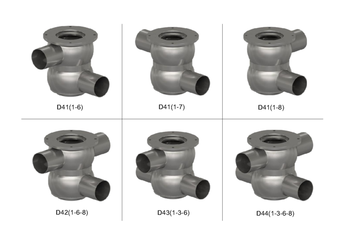
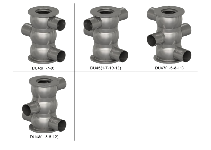
- Long housing ports ease manifold building
- Integrated shaft seal flush reduces need for external piping
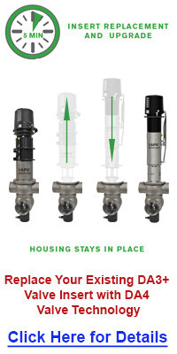
- Replacement insert available to easily upgrade existing installations
Reliable Performance
- Fully balanced design helps to prevent hydraulic blocking, withstand pressure spikes, and enables flexible flow direction without slamming
- Light overall weight helps support handling without lifting tools
- Slim stainless actuator is fully enclosed to prevent fluid ingress
- Range of control units and bus communication for automated operation
- No compressed air needed for removal and servicing
Cleanability
- Designed to the latest hygienic standards
- Standard cavity spray cleaning
- Extensive cleaning of product contact seals
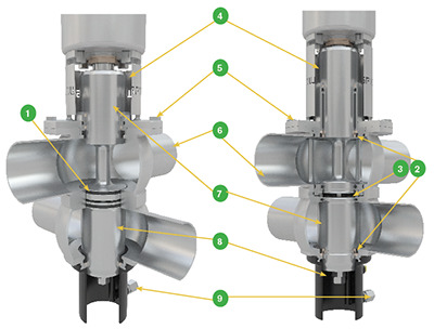
Benefits
| Valve Type | Feature | Benefit | |
|---|---|---|---|
| D4 | 1 | Radial seal design for reduced losses of product fluids during switching | - Product cost savings -Cleaner operating environment |
| Choice of seat lifting (SL) or non-seat lifting (NSL) actuator | Modular design to fit a wide range of cleanability and functionality needs | ||
| Hazardous rated options available (ATEX Zone 1 or 2) | Provides safe operation in critical applications | ||
| DA4 | 2 | Integrated upper and lower shaft seal and balancer flushing | -Extensive cleaning of product contact surfaces -Helps to reduce external flush piping |
| 3 | Metal orficies control CIP flow during seat lift | Reduces chemical and water loss consumption | |
| Replacement insert fits into existing DA3+ housing | Easy upgrade to next generation with improved features | ||
| D4 and DA4 | 4 | Open yoke design | -Reduces heat transfer from product zone into actuator - Provides visual leak detection of damaged shaft seals - Safety guard provided to reduce pinch points |
| 5 | Bolted flange connection for housing insert | - Heavy-duty, secure connection - Reliable and controlled assembly and disassembly of valve insert |
|
| 6 | Long ports to ease manifold building | Helps to reduce spool pieces and welds to ease manifold building | |
| Only two seal kit sizes used on entire range: DN40-DN65 (1.5" - 3.0") and DN80-DN100(4.0") | Reduces inventory and maintenance costs | ||
| Fully integrated sensors to detect all critical positions | - No external wires exposed to wash-down and mishandling - Extra security to monitor seat positions during cleaning |
||
| No compressed air required for servicing | Easy and efficient maintenance | ||
| 7 | Balanced upper and lower shafts (as standard) | - No hydraulic blocking - Resistant against pressure spikes - Flexibility in either flow direction through the valve (top-to-bottom or bottom-to-top) without water hammering |
|
| Reduced cleaning fluid losses to drain | - Chemical and water savings - Cleaner environment due to fewer chemicals and fluids spilling to the floor |
||
| 8 | Large separation cavity drain port | Less product risk and prevention of pressure build-up that could cause cross-contamination | |
| 9 | Flush cavity spray fixed connection (as standard) | - Enhanced cleaning - Removal of residual media in separation cavity when full CIP is not readily available - Hard-piped flush can be used without need to be removed during valve maintenance |
|
| Light overall weight | Easier handling for maintenance |
View the SPXFLOW D4 Mix Proof Valve Maintenance (Chinese) video.
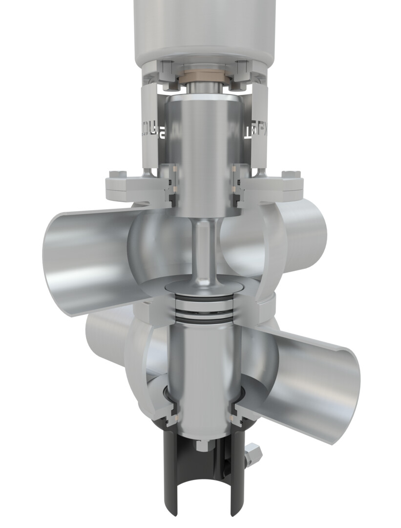
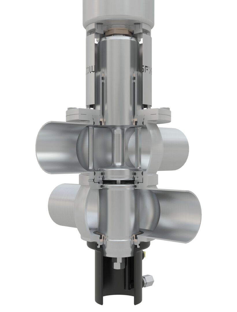
Double seat mix proof valves are used to efficiently process two different fluids (typically product and CIP) through the valve simultaneously. The mix proof design has two seats which isolate the upper and lower pipe lines when the valve is in the fail-safe closed position. The atmospheric vent cavity in between the seats creates a path for any leakage should the seals fail as well as a drain for CIP solution during seat cleaning. An external CIP spray flush is included to provide enhanced cleaning of the leakage and vent cavity while the valve is closed or open during production.
Valve Closed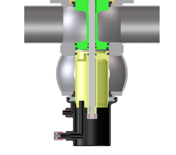 |
Optional Lower Seat Clean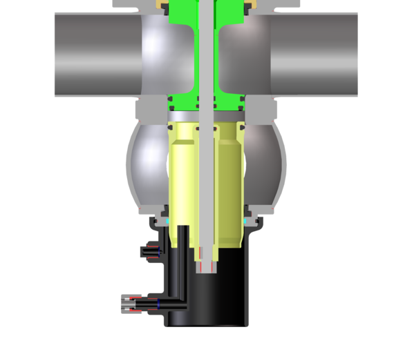 |
Valve Open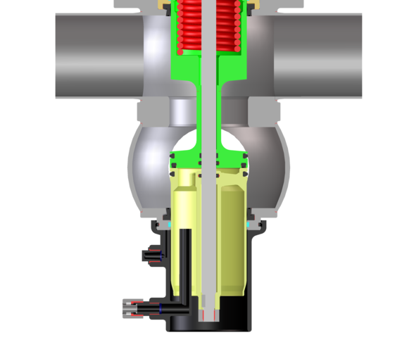 |
Optional Upper Seat Clean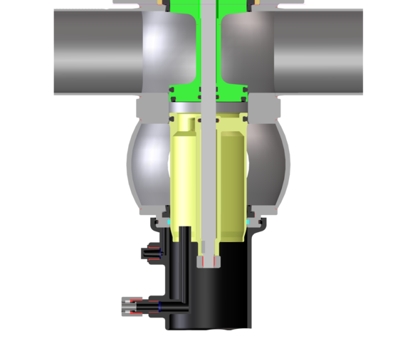 |


Food and Beverage
Soups & Sauces
Flavorings & Ingredients
Dressings, Vinegars
Soft/Fruit & Vegetable Drinks
Brewery, Wort, Wine, Distillery
Pet Food
Fats & Oils, Animal Oils
Liquid Sugar
Cereals


Personal Care and Pharmaceutical
Fluid Medicines
Extracts
Face Creams & Lotions
Perfumes
Soaps
High Purity Water
Nutritional Supplements
Hair Styling Gels & Liquids
Dyes & Alcohols


Chemical
Solvents, Paints
Adhesives
Coatings
Oils & Lubricants
Detergents
Emulsions
Fuels
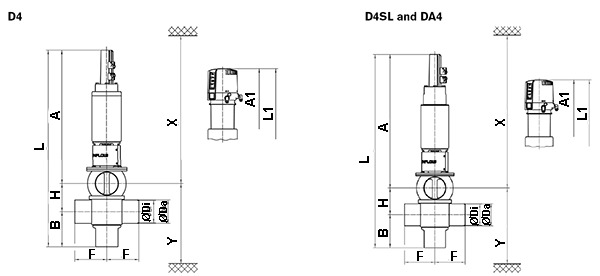
DIMENSIONS & SPECIFICATIONS
D4
| Dimensions mm | A | A1 | B | øDa | øDi | F | H | L | L1 | X* | Y* |
| DN | |||||||||||
| 40 | 483 | 566 | 120 | 41 | 38 | 125 | 63 | 666 | 749 | 820 | 200 |
| 50 | 487 | 570 | 126 | 53 | 50 | 125 | 75 | 688 | 771 | 830 | 218 |
| 65 | 495 | 578 | 134 | 70 | 66 | 125 | 91 | 720 | 803 | 840 | 242 |
| 80 | 583 | 666 | 146 | 85 | 81 | 142.5 | 106 | 835 | 918 | 930 | 274 |
| 100 | 593 | 676 | 156 | 104 | 100 | 142.5 | 125 | 874 | 957 | 940 | 303 |
| 125 | 677 | 760 | 179 | 129 | 125 | 150 | 150 | 1006 | 1089 | 1030 | 350 |
| 150 | 725 | 793 | 194 | 154 | 150 | 150 | 175 | 1094 | 1162 | 1075 | 390 |
| INCH | |||||||||||
| 1.5 | 485 | 568 | 119 | 38.1 | 34.8 | 125 | 63 | 667 | 750 | 820 | 197 |
| 2.0 | 488 | 571 | 125 | 50.8 | 47.6 | 125 | 75 | 688 | 771 | 830 | 216 |
| 2.5 | 492 | 575 | 131 | 63.5 | 60.3 | 125 | 85.3 | 708.3 | 791.3 | 840 | 233 |
| 3.0 | 498 | 581 | 137 | 76.1 | 72.9 | 125 | 97.9 | 732.9 | 815.9 | 850 | 251 |
| 4.0 | 594 | 677 | 155 | 101.6 | 97.6 | 142.5 | 125 | 874 | 957 | 840 | 301 |
| 6.0 | 726 | 795 | 193 | 152.4 | 147.3 | 149.8 | 175 | 1095 | 1161 | 1080 | 391 |
*Minimum installation and valve insert removal dimensions
D4 SL
| Dimensions mm | A | A1 | B | øDa | øDi | F | H | L | L1 | X* | Y* |
| DN | |||||||||||
| 40 | 524 | 607 | 120 | 41 | 38 | 125 | 63 | 707 | 790 | 870 | 200 |
| 50 | 528 | 611 | 126 | 53 | 50 | 125 | 75 | 729 | 812 | 880 | 218 |
| 65 | 536 | 619 | 134 | 70 | 66 | 125 | 91 | 761 | 844 | 890 | 242 |
| 80 | 618 | 701 | 146 | 85 | 81 | 142.5 | 106 | 870 | 953 | 980 | 274 |
| 100 | 628 | 711 | 156 | 104 | 100 | 142.5 | 125 | 909 | 992 | 990 | 303 |
| 125 | 677 | 760 | 179 | 129 | 125 | 150 | 150 | 1006 | 1089 | 1030 | 350 |
| 150 | 725 | 793 | 194 | 154 | 150 | 150 | 175 | 1094 | 1162 | 1075 | 390 |
| INCH | |||||||||||
| 1.5 | 526 | 609 | 119 | 38.1 | 34.8 | 125 | 63 | 708 | 791 | 870 | 197 |
| 2.0 | 529 | 612 | 125 | 50.8 | 47.6 | 125 | 75 | 729 | 812 | 880 | 216 |
| 2.5 | 534 | 617 | 131 | 63.5 | 60.3 | 125 | 85.3 | 750.3 | 833.3 | 900 | 233 |
| 3.0 | 540 | 623 | 137 | 76.1 | 72.9 | 125 | 97.9 | 774.9 | 857.9 | 900 | 251 |
| 4.0 | 629 | 712 | 155 | 101.6 | 97.6 | 142.5 | 125 | 909 | 992 | 990 | 301 |
| 6.0 | 726 | 795 | 193 | 152.4 | 147.3 | 150 | 175 | 1095 | 1161 | 1080 | 391 |
*Minimum installation and valve insert removal dimensions
DA4
| Dimensions mm | A | A1 | B | øDi | øDa | F | H | L | L1 | X* | Y* |
| DN | |||||||||||
| 40 | 589 | 672 | 120 | 38 | 41 | 125 | 63 | 772 | 855 | 930 | 200 |
| 50 | 593 | 676 | 126 | 50 | 53 | 125 | 75 | 794 | 877 | 940 | 218 |
| 65 | 601 | 684 | 134 | 66 | 70 | 125 | 91 | 826 | 909 | 950 | 242 |
| 80 | 678 | 761 | 146 | 81 | 85 | 142.5 | 106 | 930 | 1013 | 1030 | 274 |
| 100 | 688 | 771 | 156 | 100 | 104 | 142.5 | 125 | 969 | 1052 | 1040 | 303 |
| INCH | |||||||||||
| 1.5 | 588 | 671 | 119 | 34.8 | 38.1 | 125 | 63 | 770 | 853 | 930 | 197 |
| 2.0 | 594 | 677 | 125 | 47.6 | 50.8 | 125 | 75 | 794 | 877 | 940 | 216 |
| 2.5 | 598 | 681 | 131 | 60.3 | 63.5 | 125 | 85.3 | 814.3 | 897.3 | 950 | 233 |
| 3.0 | 604 | 687 | 137 | 72.9 | 76.1 | 125 | 97.9 | 838.9 | 921.9 | 960 | 251 |
| 4.0 | 689 | 772 | 155 | 97.6 | 101.6 | 142.5 | 125 | 969 | 1052 | 1050 | 301 |
*Minimum installation and valve insert removal dimensions